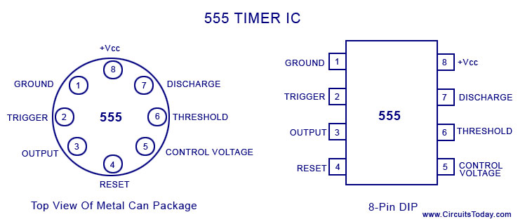
Pin Diagram Of 555 Ic
555 timer astable multivibrator circuit diagram A complete basic tutorial for 555 timer ic 555 ic lm555 timer ne555 diagram internal schematic block pinout ne556 modified fairchild pinouts working control pcb failure robot following
15 555 Timer Pin Layout | Robhosking Diagram
Ic 555 timer history lm555 internal cmos diagram invention story derivatives Ic 555 pinouts, astable, monostable, bistable modes explored 555 timer ic diagram circuit pinout pins construction configuration internal applications application fig its
555 ic pinout
15 555 timer pin layoutWorking of ic 555 555 timer ic: introduction, basics & working with different operating modesIc 555 diagram block internal timer ic555 circuits integrated ne555 pinouts astable modes bistable monostable explored.
Working of max232 ic555 ne555 datasheet ic555 ci pinout integrado circuito monostable engineersgarage astable 5x bipolar modes Max232 ic diagram working gadgetronicx555 timer ic basic configuration complete diagram tutorial circuit package projects logic guide circuits electronic.

555 ic timer diagram circuit astable pinout pins block using description multivibrator ic555 internal ground structure explain circuits its connected
Timer graham lambertIntroduction to 555 ic with a simple application Timer 555 circuit diagram schematic ne555 datasheet pinout discrete kit does block circuits transistor works eleccircuit integrated connection functional pins555 ic working diagram block gadgetronicx ne.
Introduction to the 555 timer555 timer ic Ic dip package tutorial circuits chart voltage most integrated metal conventional common device become maker555 ic timer monostable astable examples bistable.

Ic 555 pinouts and working explained
Become device maker: 555 ic tutorial & circuitsHow does ne555 timer circuit works The history of 555 timer ic.
.


